1. Overview
The SP(R) series sump pump is a vertical centrifugal slurry pump suitable for handling abrasive or corrosive slurries; the pump generally operates submerged in a sump or pit. Sump pumps are divided into the SP type and the SPR type, which share the same structure. On the SP type, the wetted parts and the shaft are made of metal, suitable for handling abrasive slurries. On the SPR type, the wetted parts are lined with corrosion-resistant rubber, suitable for handling corrosive slurries. SP(R) series sump pumps are widely used in metallurgy, mining, coal, electric power, building materials and other industries.
Model designation:
| 40 | PV | (L) | SP |
|---|---|---|---|
| Discharge diameter 40 mm | PV bearing assembly | Extended shaft series | Sump pump |
e.g. 40PV(L)SP
2. Structure Description
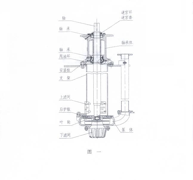
On the SP series sump pump, the casing, impeller and liner plates are all made of wear-resistant materials. The structure is simple and installation is easy. The casing is bolted to the support, and the bearing housing is mounted on the upper end of the support. The bearing housing uses a double-row tapered roller bearing on the pump end and a single-row cylindrical roller bearing on the drive end, capable of withstanding the maximum axial load of the pump. A motor base or motor support is mounted on the bearing housing; either direct drive or V-belt drive may be used, and the sheaves can be conveniently changed to vary the pump speed to accommodate changes in operating conditions or changes in performance after the pump wears. The support carries a split mounting plate, which can be conveniently set on a steel-frame foundation or a concrete foundation. The pump should operate submerged in the slurry sump. The pump inlet is fitted with a strainer to prevent large particles from entering the pump.
The structure of the SPR type pump is exactly the same as that of the SP type pump; the only difference is that all parts submerged in the slurry are lined with corrosion-resistant rubber. The rubber-lined parts include the shaft, casing, impeller, liner plates and strainer. The connecting bolts in the submerged section are all fitted with rubber protective sleeves, and the drive-end parts are exactly the same as those of the SP type pump.
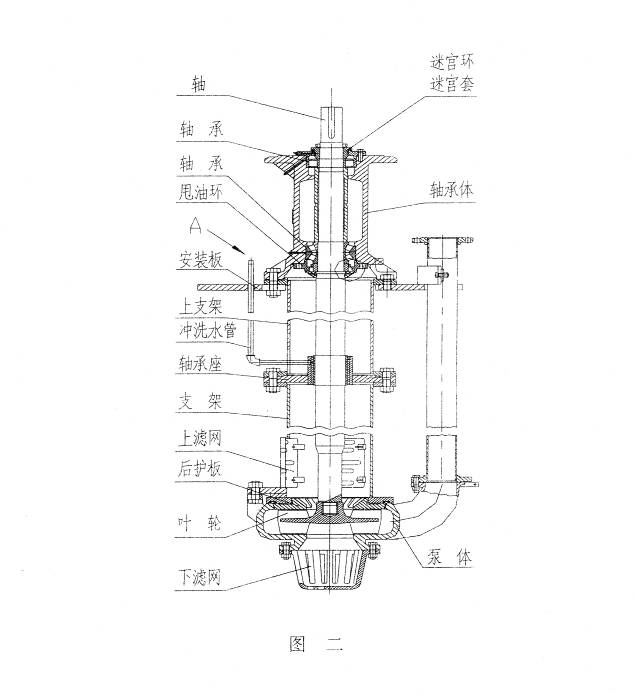
The extended shaft series adds a guide bearing section and is equipped with a flush water pipe. The flush water pressure, flow rate and flush water pipe size are given in the table below.
| Pump model | Water pressure (MPa) | Water flow (l/s) | Size | Pump model | Water pressure (MPa) | Water flow (l/s) | Size |
|---|---|---|---|---|---|---|---|
| 40PVL-SP | ≥0.2 | 1 | 3/8″ | 100RVL-SP | ≥0.2 | 1 | 3/8″ |
| 40PVL-SPR | ≥0.2 | 1 | 3/8″ | 100RVL-SPR | ≥0.3 | 1.2 | 3/8″ |
| 65QVL-SP | ≥0.2 | 1 | 3/8″ | 150SVL-SP | ≥0.2 | 4 | 3/4″ |
| 65QVL-SPR | ≥0.2 | 1 | 3/8″ | 250TVL-SP (special) | ≥0.3 | 5 | 3/4″ |
| 65QVL-SP (special) | ≥0.3 | 2 | 3/8″ |
3. Assembly Precautions
1. Assembling the bearing assembly
Before assembling the bearings, the bearing assembly must be preheated; the temperature must not exceed 120 °C. The lower bearing is a double-row tapered roller bearing; its inner ring, outer ring, locating sleeve, etc. form a matched set and must not be interchanged with the corresponding parts of similar bearings. When installing the lower bearing end cover, make sure that the lip of the lip seal in the groove of the lower end cover faces outward. The oil slinger and other parts must be positioned as shown in the assembly drawing. When installing the labyrinth rings, make sure that the openings of the labyrinth rings are staggered in the diametral direction. Since the bearings themselves already guarantee the axial clearance, the bearing assembly of the sump pump requires no clearance adjustment during assembly; however, once assembly is complete, it is recommended that the installed face clearance be checked against the values listed in the table below.
| Bearing assembly | Face clearance (mm) |
|---|---|
| PV | 0.074 ~ 0.160 |
| QV | 0.114 ~ 0.208 |
| RV | 0.084 ~ 0.211 |
| SV | 0.064 ~ 0.206 |
| TV | 0.127 ~ 0.259 |
2. Installing the support, mounting plate and casing
Bolt the bearing assembly to the support, fit the split mounting plate around the periphery of the support and secure it to the support with studs, then install the frame plate liner, impeller and casing. During assembly, pay attention to the relative positions of the bearing housing, support, mounting plate and casing, which must conform to the figure below so as to ensure the relative positions of the discharge pipe and the grease nipples; see Fig. 3.
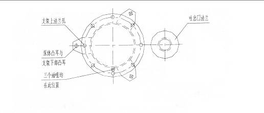
The connecting bolts between the support and the casing must be tightened. Check whether the impeller rotates smoothly; if there is any rubbing, adjustment can be made by adding shims at the connecting bolts between the bearing housing and the support. Finally, install the upper and lower strainers and the discharge pipe; the upper part of the discharge pipe is fixed to the mounting plate with screws.
4. Operation
1. Startup
Before starting, inspect the entire unit according to the following steps:
(1) The pump should be mounted on a solid foundation to carry the entire weight of the pump and eliminate vibration; tighten all foundation bolts.
(2) The piping and valves should be independently supported. There are gaskets at the pump flanges; when tightening the connecting bolts, pay attention to the sealing face height of the pump flange, and the bolts must not be overtightened, so as to avoid damaging the sealing faces.
(3) Turn the shaft by hand in the pump's direction of rotation; the shaft should be able to drive the impeller without any rubbing, otherwise the impeller clearance should be adjusted.
(4) Check the motor rotation direction and make sure the pump rotates in the direction of the arrow marked on the casing. Note that reverse rotation of the pump is not permitted, otherwise the impeller thread will strip, causing damage to the pump.
(5) With direct drive, the pump shaft and the motor shaft must be precisely aligned; with V-belt drive, the pump shaft and the motor shaft must be parallel, and the sheave positions must be adjusted so that the V-belts are square to the sheaves, so as to avoid severe vibration and wear.
When SPA and  type, and SPB and
  type sheaves are used in matched sets, adjust the sheaves to meet the requirement α1 = α2 shown in Fig. 5.
(6) Finally, check once more that all nuts are tightened and that the shaft rotates freely; then connect the guide bearing flush water at point A shown in Fig. 2 and, 5 minutes later, start the pump. Before pumping slurry, it is best to start the pump on clean water first.
2. Running
During operation, observe the various instruments and check the pump velocity, flow and current. If the flow decreases, the power drops, or the discharge pressure falls or ceases during operation, this is most likely caused by large particles blocking the strainer, the suction inlet or the impeller passages; blockage may also occur when large particles accumulate heavily in the discharge pipe, preventing the pump from working normally. Be sure to clear any blockage promptly. If the pump is not installed level, it will vibrate.
3. Stopping the pump
If possible, run the pump on clean water for a while before stopping it, to clear the slurry out of the pump and the piping. Stop the pump first and then close the valves; turn off the guide bearing flush water 5 minutes after the pump stops.
Note: 1. During operation, the liquid level must not rise above the position of the mounting plate shown in Fig. 1 and Fig. 2, to prevent water from entering the bearings;
2. The guide bearing flush water must be clean water
4. Adjusting the V-belt pre-tension
The adjustment method recommended by our factory is described below for reference.
(1) First calculate the pre-tension Q
 (N)
(N)
(2) Look up the value of e on the curve according to the pre-tension and the V-belt section.
(3) Calculate f from the formula.

(4) Look up the value of R for the corresponding V-belt section in Table 1. Following the method shown in Fig. 4, reach the required pre-tension Q by adjusting the center distance between the two sheaves. Generally, when a force of R newtons is applied, the required pre-tension Q is reached once the total deflection of the free span is no greater than f.
Where: Q – minimum static pre-tension of the free span per V-belt, in newtons
f – total deflection of the V-belt free span, in mm
C1 – angle coefficient, approximately 0.9
C2 – service coefficient, approximately 1.4
L′ – center distance between the sheaves
P – motor rated power, kW
Z – number of V-belts
V – belt speed, m/s
m – centrifugal coefficient (see Table 1)
e – deflection per 100 mm of free span length, see Fig. 4
Table 1
| Section | SPA | SPB | SPC | SPZ |
|---|---|---|---|---|
| R | 60 | 90 | 120 | 30 |
| m | 0.12 | 0.20 | 0.38 | 0.08 |
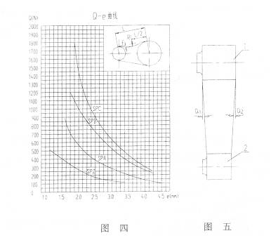
Note: In Table 1 the value of R is in newtons; in Fig. 5, item 1 is the pump sheave and item 2 is the motor sheave.
The V-belts should be adjusted to a final pre-tension such that the pre-tension is at a minimum when the load is at its maximum. When V-belts are used as a set, the circumference of each belt should be essentially identical, so that every V-belt carries an equal load during operation.
After the V-belts have been adjusted, check once more whether the impeller rotates normally. Where possible, start the pump on clean water before pumping slurry. Start the motor and check the discharge pressure and flow.
5. Maintenance
SP(R) series pumps are ruggedly built and durable; if correctly installed and operated, the pump will have a long service life, but attention must be paid to maintenance in the following aspects:
Impeller adjustment and replacement
The clearance between the impeller and the casing of the SP(R) series pump should be maintained at approximately 0.5–1 mm (the clearance can be adjusted by adjusting the shims between the bearing housing and the support), so that the pump runs at high efficiency. When the impeller and the casing are worn to the point that the performance and efficiency of the pump drop severely and can no longer meet the operational requirements, the worn parts should be replaced.
Bearing lubrication
An appropriate amount of grease is already added to the bearings during assembly. During operation, grease can be added periodically through the two grease nipples on the bearing housing. The amount of grease must not be excessive, as too much grease will cause the bearings to heat up. The greasing interval and quantity vary considerably with the operating conditions, and experience should be accumulated gradually in use. Note that the grease must be kept clean and that no dirt is allowed to enter it. Under normal continuous operation, the bearing greasing intervals may be referenced from Table 2. Lithium-based grease No. 2 or No. 3 is recommended for the bearing grease, and the amount of grease to be used per bearing at initial assembly may be referenced from Table 3.
3. When a standby pump is left idle for a long time, it is recommended to turn it by hand 1/4 of a revolution each week, so that the rolling bearings are loaded evenly.
Table 3
| Bearing assembly | Drive end (g) | Pump end (g) |
|---|---|---|
| PV | 60 | 90 |
| QV | 130 | 225 |
| RV | 300 | 450 |
| SV | 400 | 550 |
| TV | 450 | 2200 |
6. Possible faults and solutions
| Fault | Cause | Solution |
|---|---|---|
| Pump fails to draw water | Wrong rotation direction or damaged impeller Suction pipe blocked |
Check the rotation direction, fit a new impeller Clear the blockage |
| Excessive shaft power | Rubbing inside the pump Damaged bearings Drive belts too tight Pump flow too high Speed too high, high specific gravity Motor shaft misaligned with or not parallel to the pump shaft |
Eliminate the rubbing Replace the bearings Adjust the belts Adjust the pump operating conditions Adjust the speed Align the motor shaft and the pump shaft |
| Bearings overheat | Too much or too little grease Contamination in the grease Damaged bearings |
Add the correct amount of grease Replace with fresh grease Fit new bearings |
| Short bearing life | Motor shaft misaligned with or not parallel to the pump shaft Bent shaft Rubbing inside the pump or impeller out of balance Foreign matter in the bearings or improper grease quantity Improper bearing assembly |
Align the motor shaft and the pump shaft Replace the shaft Eliminate the rubbing, fit a new impeller Clean the bearings Replace the bearings or reassemble the bearings |
| Pump vibrates with high noise | Damaged bearings Impeller out of balance Non-uniform flow, pump running dry |
Fit new bearings Fit a new impeller Improve the pump feed conditions |